The Weasley Clock project started in part because my grandfather clock broke. I even tried putting a new clock mechanism in it and it still did not work. I can see it was just waiting for the LabVIEW Community Edition to come out so it could be made into something better.
Before Pictures
First off, here are some before picture showing the old grandfather clock. As you can see from the pictures, it wasn’t a real mechanical grandfather clock. It had a regular clock mechanism that ran on a AA battery and another mechanism to run the pendulum and play electronic chimes that ran on two D batteries. I decided to resuse the pendulum mechanism but connect it to the Raspberry Pi. Everything else has been removed.
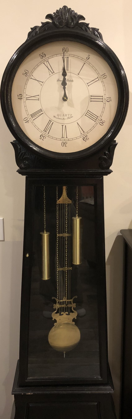
Old Grandfather Clock-Front View
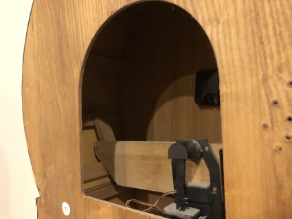
Old Grandfather Clock-Back, Top View
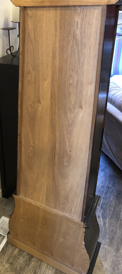
Old Grandfather Clock-Back, Bottom View
Size Constraints
The main constraint is that there is only 8.25 inches from the back of the glass to the back of the clock and about 16 to 17 inches diameter. In that space the following needs to fit:
- the new Clock Face
- seven servos
- all of the gears
- the clock hands and nested shafts
- seven Arduino Nanos
- a Raspberry Pi with the AdaFruit Servo Hat each with their own power supply
- a powered USB Hub for the Arduinos with power supply
- a power bar/surge protector
- speakers
- the pendulum mechanism
Cut Open-Back Top View
Utilizing the Base
This was going to be a lot to cram in there. After talking with my coworkers about the problem, I realized that the base of the grandfather clock was hollow. I wondered if I could cut a hole through the back and use it for the Arduinos, Raspberry Pi, USB Hub, and power supplies.
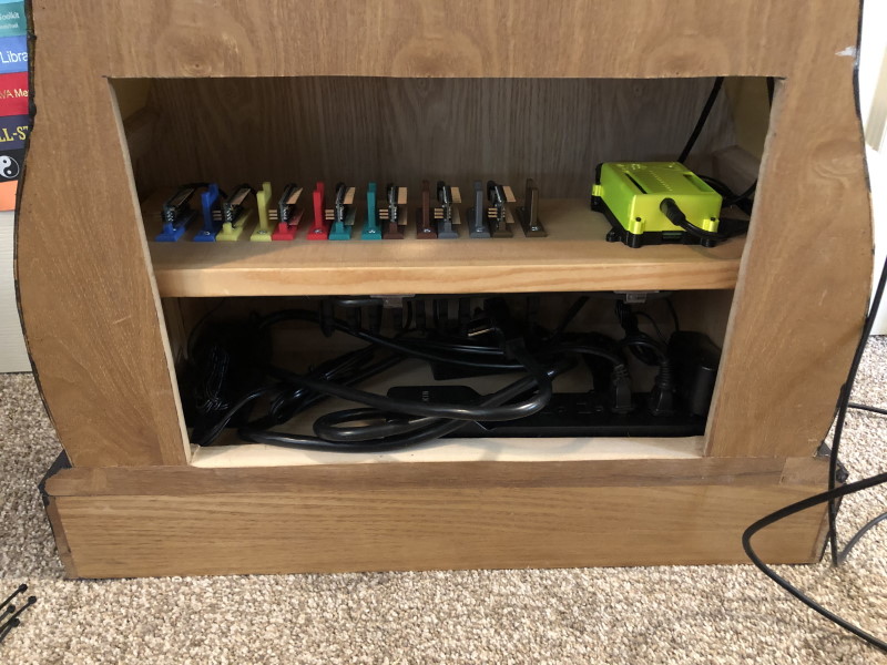
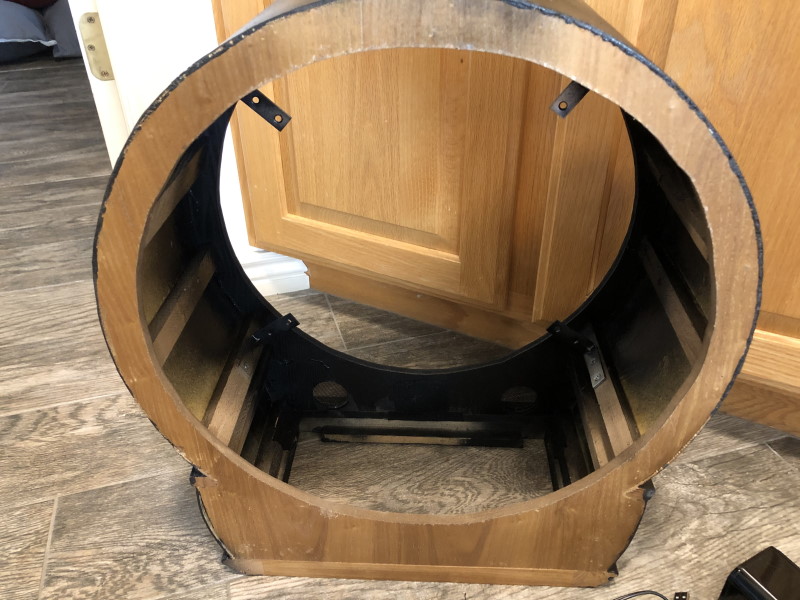
Cut Open-Back Bottom View
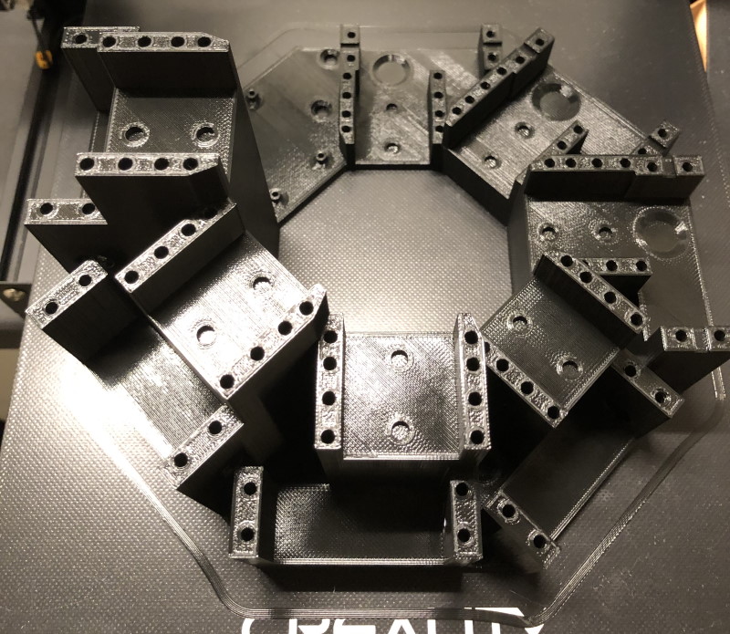
3D Printing
Before I bought the Ender 3 Pro 3D printer I was trying hard to figure out how to create all of the fixtures out of wood. The first design I created barely fit the servos and gears. I hadn’t even got to the rest of the components and this was while I was going to be putting it all in the top.
After my printer came I found Thingiverse and found it had brackets and cases for Arduinos and Raspberry Pis.
Arduino Brackets
For the Arduino brackets I started using DaveGadgeteer’s design from Thingiverse but I quickly ran into troubles as I kept breaking off the arms trying to get the Arduinos in.
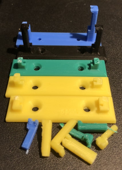
Failed Arduino Brackets
Whether by frustration or inspiration, I tried snapping an Arduino in a broken one and realized it didn’t need the arms. I designed my own and printed one for each Arduino Nano. I later printed wire guides to match as well.
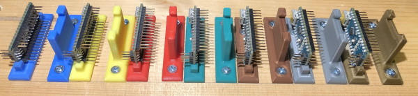
Finished Arduino Brackets
Raspberry Pi with Servo Hat Case
For the Raspberry Pi I found this case by jferguson368 which was made for the Pi and the AdaFruit Servo Hat. I printed it and was planning on using it but realized that it didn’t have an opening for the passthrough pins, but only for the servo pins. I still use the base part as is but I modified his design of the top and added a bit of flair to it as well.
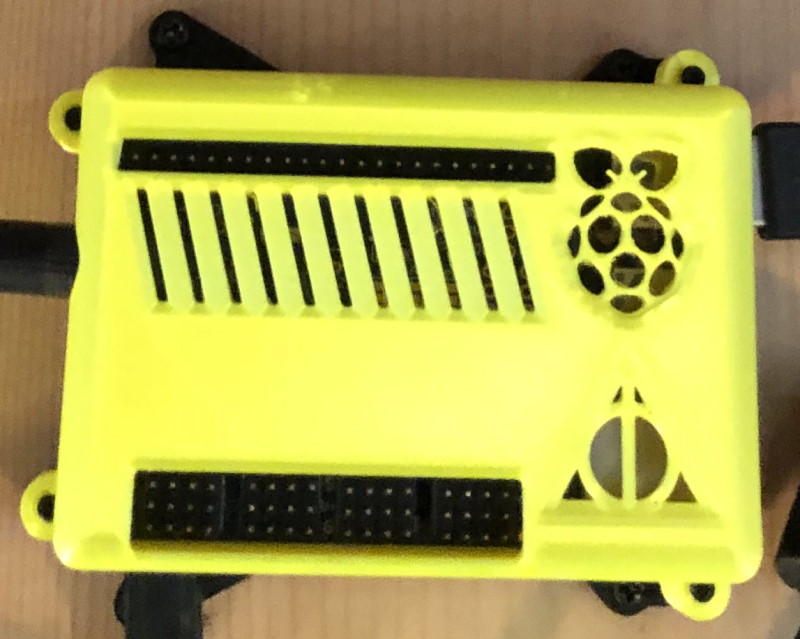
Raspberry Pi with AdaFruit Servo Hat Case
Servo Bracket
This was the most complicated thing I have 3D printed but I am very happy with the result. Without all of the features, I would not have been able to get the gears and servos to fit.
Servo Bracket
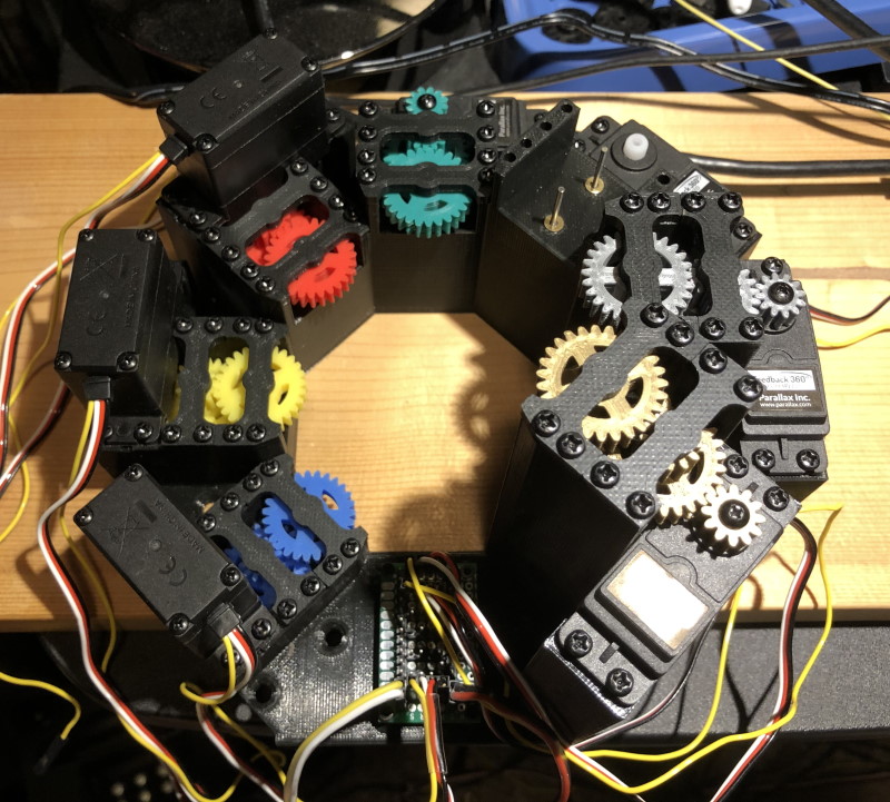
Servo Bracket with Gears
Pendulum Bracket
Initially, I was going to mount the pendulum mechanism directly to the back of the clock face. However, the speaker was in the way and it would be hard to route the servo wires. So I create this bracket to allow the servo wires to pass under it.
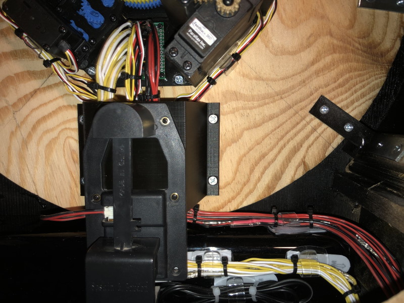
Pendulum Bracket
Now that it all fits time to show the wire routing.